Post #1
This article shows the DB15 BOOT cable pinout used with KESS V2 Master and K-TAG / KTAG ECU Master ECU flashers.
In some cases, users may experience no communication with the ECU when connecting in BOOT mode. One of the common reasons is an incorrect DB15 cable pinout or a BOOT cable wired for another device.
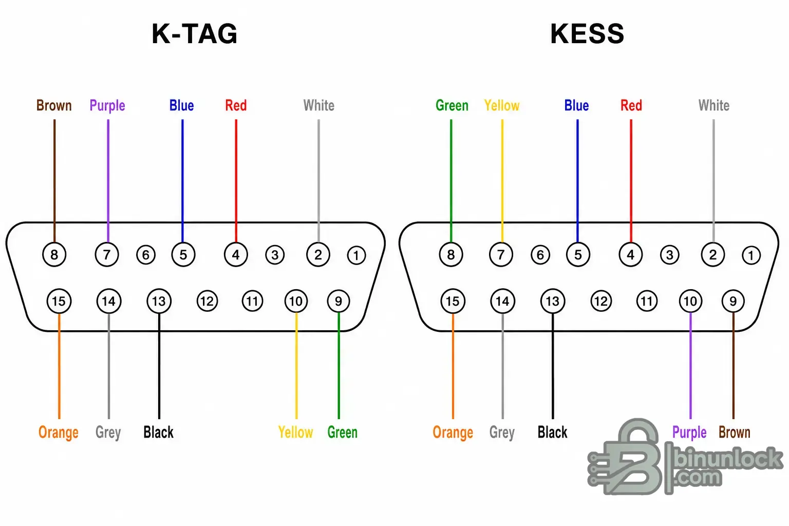
Although the DB15 cable from K-TAG ECU Master looks identical to the DB15 cable from KESS V2 Master, these cables have different pinouts.
This means that a KESS V2 DB15 BOOT cable is not suitable for K-TAG / KTAG ECU Master, and a K-TAG DB15 BOOT cable is not suitable for KESS V2 Master.
To check your BOOT cable, open the DB15 connector housing and compare the wiring with the pinout diagram. The main differences are related to the brown and green wires, as well as the yellow and purple wires.
The main difference between the KESS V2 DB15 BOOT cable pinout and the K-TAG / KTAG DB15 BOOT cable pinout is that the Brown/Green and Yellow/Purple wire pairs are swapped.
Some DB15 BOOT breakout cables may include duplicated power and ground wires, such as two red wires for ECU power, two orange wires for key switched power and two black wires for ground.
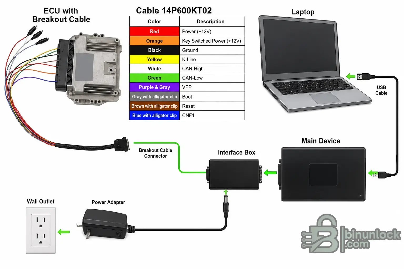
A correctly wired DB15 BOOT cable is required for stable ECU communication in BOOT mode via K-Line and CAN. Before troubleshooting the ECU, software, drivers or the interface box, always verify that the DB15 cable pinout matches your device: KESS V2 or K-TAG / KTAG.
In some cases, users may experience no communication with the ECU when connecting in BOOT mode. One of the common reasons is an incorrect DB15 cable pinout or a BOOT cable wired for another device.
KESS V2 and K-TAG DB15 cables are not interchangeable#
Although the DB15 cable from K-TAG ECU Master looks identical to the DB15 cable from KESS V2 Master, these cables have different pinouts.
This means that a KESS V2 DB15 BOOT cable is not suitable for K-TAG / KTAG ECU Master, and a K-TAG DB15 BOOT cable is not suitable for KESS V2 Master.
To check your BOOT cable, open the DB15 connector housing and compare the wiring with the pinout diagram. The main differences are related to the brown and green wires, as well as the yellow and purple wires.
KESS V2 vs K-TAG DB15 BOOT cable pinout differences#
- Pin 8 — K-TAG: Brown / RESET; KESS V2: Green / CAN-L
- Pin 7 — K-TAG: Purple / VPP; KESS V2: Yellow / K-Line
- Pin 9 — K-TAG: Green / CAN-L; KESS V2: Brown / RESET
- Pin 10 — K-TAG: Yellow / K-Line; KESS V2: Purple / VPP
The main difference between the KESS V2 DB15 BOOT cable pinout and the K-TAG / KTAG DB15 BOOT cable pinout is that the Brown/Green and Yellow/Purple wire pairs are swapped.
DB15 BOOT cable wire color functions#
- GREEN — CAN-L
- ORANGE — VKEY / key switched power +12V
- YELLOW — K-Line
- RED — VECU / ECU power +12V
- BLACK — Ground / GND
- PURPLE — VPP
- WHITE — CAN-H
- BROWN — RESET
- GRAY — BOOT
- BLUE — CNF1
Some DB15 BOOT breakout cables may include duplicated power and ground wires, such as two red wires for ECU power, two orange wires for key switched power and two black wires for ground.
A correctly wired DB15 BOOT cable is required for stable ECU communication in BOOT mode via K-Line and CAN. Before troubleshooting the ECU, software, drivers or the interface box, always verify that the DB15 cable pinout matches your device: KESS V2 or K-TAG / KTAG.


