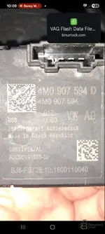
Subject: Bricked Sunroof Control Module (4M0 907 594 D) after coding - No communication

Post #1

zoli

Watchlisted

Hungary
Joined
24.11.2025
Messages
2
Reactions
0
Location
Hungary
Hello,
I have a sunroof control module with part number 4M0 907 594 D that no longer responds (bricked) due to excessive/incorrect coding attempts. The diagnostic tool cannot communicate with the module at all; it is not visible on the CAN gateway.
I am looking for the following information:
Is there a known “wake-up” or recovery method for reviving the module?
Does anyone have a working flash dump (EEPROM/Flash content) that could be reloaded onto the device?
Does anyone have the pinout diagram for this module so that I can try connecting the padba?
Any help would be greatly appreciated. Thank you!
 
Ratings and Reviews
Total ratings: 0

Post #2

Hello,
I have a sunroof control module with part number 4M0 907 594 D that, due to excessive/incorrect coding ...

Hi!

I'm sorry this happened to you. The 4M0 907 594 D modules (MLB Evo platform) are quite sensitive to coding and parameterization. If diagnostics (VCDS/ODIS) cannot see it, the module is probably stuck in "boot mode," or CAN communication has stopped completely due to a software error.

A few recovery tips:

  • First, try a "hard reset": disconnect the negative terminal of the car battery for 15–20 minutes. Sometimes the controller is simply frozen, and disconnecting the power restarts the CAN transceiver.
  • If that does not help, you should definitely try it on the bench. In the car, the Gateway may disable communication if the module sends faulty data to the bus or if the bus is "silent."

Pinout:
Although the exact wiring diagram would require the vehicle's exact model and model year (e.g. Q7 4M), the general logic for VAG roof modules is as follows:

Code:
Nagyobb érintkezők (Tápellátás):
Pin 1 (vagy piros/fehér vezeték helye): +12V (Terminal 30 - állandó táp)
Pin 2 (vagy barna vezeték helye): GND (Terminal 31 - test)

Kisebb érintkezők (Kommunikáció):
CAN High: Narancs/Zöld (általában)
CAN Low: Narancs/Barna (általában)

Bench recovery:
1. Connect the power supply and the CAN lines.
2. IMPORTANT: On the bench, connect a 120 Ohm termination resistor between CAN High and CAN Low, otherwise there will be no communication.
3. Try accessing it with VCP (Vag Can Pro) or ODIS Engineering. If successful, flash it again with the factory .frf or .sgo container file.
4. After flashing, you will need parameterization (ZDC file / XML dataset), because flashing alone usually erases the calibration.

If the EEPROM is damaged, unfortunately you will need to open the housing and read the processor (MCU) directly with a programmer (e.g. VVDI Prog, Orange5), but hopefully bench flashing will solve it.

Good luck!
 

Post #3

2017 VW Touran

Thank you for the clarification. This is an important detail because there is a technical contradiction here that you need to pay attention to during the repair.

The 4M0 907 594 D part-number module belongs to the MLB Evo platform (e.g. Audi Q7 4M, Audi A4 B9), and it is a standalone CAN-bus controller.
The 2017 VW Touran, on the other hand, is based on the MQB platform, where the sunroof controller (J245) normally communicates via the LIN bus from the factory and is a “slave” module (subsystem) of the 09 BCM (Central Electronics).

If you are sure that this 4M0 module is suitable for this vehicle (or that this is a retrofit), then the pinout of the module (and not the Touran’s factory wiring harness) for bench activation is as follows, based on the Audi wiring diagrams:

Connector: 10-pin black

  • Pin 1: +12V (Terminal 30 - Permanent power)
  • Pin 6: GND (Terminal 31 - Ground)
  • Pin 3: CAN High (Comfort or Extended CAN)
  • Pin 2: CAN Low (Comfort or Extended CAN)

Bench steps:
1. Connect the above 4 wires to a suitable power supply and the diagnostic interface.
2. Critical: Place a 120-ohm terminating resistor between CAN High and CAN Low; otherwise, the diagnostic tool will not communicate with the module on the bench.
3. Try connecting using ODIS Engineering or VCP. If the hardware is not damaged, it should respond, and you will be able to flash it again with the correct container file.

If the vehicle is factory-original and the module is original, it is worth checking the part number again, because Tourans generally use LIN modules beginning with 5Q0... or 5G0.... If the module is LIN-based, you will not be able to access it directly via CAN, only through a LIN interface or a working BCM.
 

Post #4

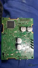
"Hello everyone,
I am looking for the connection points for an Audi sunroof control module. Could someone share the trunk mode and bench mode pinouts for this specific unit?
I need to reflash the firmware-t/tartalmat, because the module does not respond via OBD."
 

Attachments

  • 20260219_100225.webp
    20260219_100225.webp
    1.1 MB · Views: 154
  • Screenshot_20260219_100911_Viber.webp
    Screenshot_20260219_100911_Viber.webp
    135.2 KB · Views: 150
  • 20260219_100225.webp
    20260219_100225.webp
    1.1 MB · Views: 167

Post #5

"Hello everyone,
I am looking for the connection points for an Audi sunroof control module. Could someone...

Hi!

There is a difference between “trunk mode” (I assume you mean Boot mode, based on the translation) and connecting it on the bench (Bench mode). It is worth trying through the external connector first.

The pinout of the 10-pin connector on the 4M0 907 594 D (and most similar MLB Evo Webasto modules) is as follows:

Bench Pinout (External connector)

  • Pin 1: +12V (Power supply / Terminal 30)
  • Pin 6: GND (Ground / Terminal 31)
  • Pin 3: CAN High
  • Pin 2: CAN Low

Important: If you are testing it on the bench, connect a 120-ohm resistor between CAN High and CAN Low; otherwise, the diagnostic tool will not be able to communicate with the module.

Boot Mode (Direct MCU access)

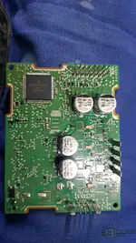
If CAN communication is completely dead and you cannot access it via ODIS Engineering or VCP even with the wiring above, you will need to open the housing.
This module generally contains a Renesas processor (e.g. the V850 or RH850 series) or an ST processor. There is no standardized “boot pin” on the external connector; you need to locate the programming points on the PCB (JTAG or UART interface), which would require the exact MCU marking.

I recommend first trying the above 4-wire connection with the resistor. If that still does not work, open the housing and send a picture of the PCB or processor."
 

Post #6

Please, does anyone know where i can get the the factory .frf or .sgo container file for black bosch mlb cluster 8w5920790M? It does talk to odis engineering.
 
Activity
So far there's no one here