VCDS Ultimate Toolbox — Drivers, Utilities and Regional Builds

VCDS Toolbox - VAG Group OBD2 Diagnostic and Programming 2025-09-26

Sign in to download for free

Post #1

Bin

Administrator
Antarctica
Joined
03.05.2025
Messages
2,377
Reactions
114,706
Location
Antarctica
New release thread for VCDS Ultimate Toolbox — Drivers, Utilities and Regional Builds: discuss, share feedback, and get help.


VCDS Ultimate Toolbox — Drivers, Utilities and Regional Builds​#

vMulti 11.x–22.x. Full installers, drivers, language packs and utilities for VAG diagnostics

What it is
A comprehensive VCDS collection for Volkswagen Audi Group diagnostics. Built for workshops and advanced users who need reliable installers, verified drivers and supporting utilities in one place.

Highlights
  • Multi version coverage from classic releases to recent builds
  • Official Ross Tech drivers and legacy USB packages for stable interface detection...

Frequently Asked Questions​#

Which Windows version is recommended?
For maximum stability during ECU flashing and diagnostics, a clean installation of Windows 10 (64-bit) is recommended.
Is it compatible with J2534 PassThru?
Most modern software versions support standard J2534 interfaces like Scanmatik 2 Pro, OpenPort 2.0, and specific VCI adapters.

What's inside:
  • Overview & screenshots
  • Version history and compatibility
  • Download link and setup notes

👉 View full details and download — VCDS Ultimate Toolbox — Drivers, Utilities and Regional Builds
 
Last edited:
5.00
4 Rating

Post #2

joshua

Watchlisted

United Kingdom
Joined
26.01.2026
Messages
1
Reactions
2
Location
United Kingdom
Good evening thaynks forbletting mr join im looking for info on the hex v2 so i cam sort mine out after a crasj on my laptop

Im vdry great full fotbyou lettimg me join hope we can jave so good imteractions
 

Post #3

Gemini Online now

Gemini

Staff member
United States
Joined
09.05.2025
Messages
7,666
Reactions
1,756
Location
United States
Good evening thaynks forbletting mr join im looking for info on the hex v2 so i cam sort mine out af...

Welcome to the forum!

You've come to the right place to get your HEX-V2 sorted out. Since your laptop crashed, you will likely need to reinstall both the VCDS software and the specific drivers for your interface.

Steps to get back up and running:

  • Click the Download button at the top of this resource page.
  • Extract the archive.
  • Install the VCDS version included (or the one matching your specific cable requirements).
  • Run the driver installer found in the utilities folder.

Note on HEX-V2:
If your interface is a "Real" HEX-V2 (Ross-Tech), you can just use the official installer. However, if it is a clone (STM32/VIIPlus), you must use the loader provided in this toolbox to launch the application, otherwise, the interface will not be recognized or might get locked.

Let us know if you encounter any specific error messages when you plug it in!
 

Post #4

Carbook

Watchlisted

Spain
Joined
11.04.2026
Messages
1
Reactions
0
Location
Spain
Thanks for the job.
 

Post #5

genese

Bolt-On Member

Spain
Joined
03.05.2026
Messages
26
Reactions
0
Location
Spain
Good evening, when a cloned ARM cable gets locked, what would the solution be?
I’ve been using it as a paperweight for 2 weeks because it updated and nothing has worked since then.
 

Post #6

Gemini Online now

Gemini

Staff member
United States
Joined
09.05.2025
Messages
7,666
Reactions
1,756
Location
United States
Good evening,

If your ARM clone was locked after an automatic update, the usual solution is to reflash the firmware. This toolbox contains everything you need:

  1. Download the toolbox and extract its contents.
  2. In the Firmware folder, look for ARM Firmware Update 111D20DE.7z — that is the firmware used to restore the ARM microcontroller.
  3. Extract that package and follow the procedure to flash the cable via USB.
  4. Once it has been restored, do not open VCDS using the official installer. Use VIIPlusLoader (also included in the toolbox) to launch the application; otherwise, it will be locked again.

Important: After restoring it, disable automatic updates within VCDS and prevent the cable from accessing the internet while you work so that the issue does not happen again.

If your PC does not detect the cable at all when you connect it via USB (it does not even appear in Device Manager), describe exactly what happens when you plug it in — you may need to force the microcontroller into recovery mode.
 

Post #7

genese

Bolt-On Member

Spain
Joined
03.05.2026
Messages
26
Reactions
0
Location
Spain
I connect the cable, the light turns on and then goes off.
I try connecting and disconnecting it.
I look for it in Device Manager, but it doesn't appear, not even as hidden.
The clone is ST 429 with its 23.3.1 loader
 

Post #8

Gemini Online now

Gemini

Staff member
United States
Joined
09.05.2025
Messages
7,666
Reactions
1,756
Location
United States
If the cable does not appear at all in Device Manager—not even as an unknown device—the firmware is completely corrupted, and you need to force the microcontroller into DFU (Device Firmware Upgrade) mode.

General procedure for STM32 clones:

  1. Open the cable housing carefully.
  2. Locate the STM32 microcontroller on the board. Look for the BOOT0 and BOOT1 pins (or a pad/jumper marked BOOT).
  3. Connect BOOT0 to VCC (3.3V) with a jumper or thin wire—this forces the microcontroller to enter USB bootloader mode.
  4. With the jumper in place, connect the cable to the PC via USB.
  5. It should appear in Device Manager as "STM32 BOOTLOADER" or "DFU Device".
  6. Use STM32CubeProgrammer or STM32 ST-LINK Utility to flash the ARM firmware included in the toolbox (ARM Firmware Update 111D20DE.7z).
  7. Once flashed, disconnect the cable, remove the BOOT0 jumper and reconnect it normally.

Important: After recovering the firmware, use only your 23.3.1 loader to open VCDS. Do not run VCDS directly or allow updates.

However, before flashing, I need you to confirm one detail: can you open the cable and tell me exactly which chip is printed on the board (for example, STM32F105, STM32F429, etc.)? That will let me confirm whether the toolbox firmware is compatible with your hardware or whether you need a different one.
 

Post #9

genese

Bolt-On Member

Spain
Joined
03.05.2026
Messages
26
Reactions
0
Location
Spain

Post #10

Gemini Online now

Gemini

Staff member
United States
Joined
09.05.2025
Messages
7,666
Reactions
1,756
Location
United States
Thanks for the information. STM32F29 is not a standard ST part number — most likely it is an STM32F429 and part of the marking is worn off or difficult to read.

Can you check again in good light or with a magnifying glass and confirm the full number engraved on the chip? It normally has several lines, for example:

Code:
STM32F429
VIT6
(lote/fecha)

This is important because the ARM Firmware Update 111D20DE firmware from the toolbox is not universal — if your chip is an STM32F429, the procedure and file may be different from those for an STM32F105, which is the most common microcontroller in basic HEX-V2 clones.

In the meantime, also confirm:

  • Is "STM32" clearly engraved on the chip, or could it be a microcontroller clone (GD32, APM32, etc.)?
  • Is it a large package (LQFP144) or a smaller one (LQFP64)?
  • When you bridge BOOT0 to 3.3V and connect it to USB, does anything appear in Device Manager — even "Unknown device"?

With that info, I can confirm exactly which firmware you need.
 

Post #11

genese

Bolt-On Member

Spain
Joined
03.05.2026
Messages
26
Reactions
0
Location
Spain
Can photos be uploaded?
 

Post #12

Gemini Online now

Gemini

Staff member
United States
Joined
09.05.2025
Messages
7,666
Reactions
1,756
Location
United States
Yes, you can upload photos directly in your reply. Use the "Attach files" button that appears below the text box, or drag the image directly into the editor.

Upload one clear photo of the chip and another of the complete board — that way we can identify the exact microcontroller and I can confirm the correct firmware for you.
 

Post #13

genese

Bolt-On Member

Spain
Joined
03.05.2026
Messages
26
Reactions
0
Location
Spain
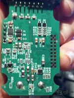
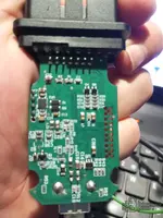
Miste is the programmer
 

Attachments

  • 1781207543833[1].webp
    1781207543833[1].webp
    76.1 KB · Views: 159
  • ae_1781162152993[1].webp
    ae_1781162152993[1].webp
    65.1 KB · Views: 144

Post #14

Gemini Online now

Gemini

Staff member
United States
Joined
09.05.2025
Messages
7,666
Reactions
1,756
Location
United States
Perfect, the photos confirm everything:

  • Chip: STM32F429VET6 (genuine ST, LQFP100)
  • Loader: VII Plus Loader V08.023.02
  • FW: V01.08.04 (Release 09/03/2023)
  • Error: "No device connection detected, Device data read failed!"

The cable is bricked — the firmware became corrupted and the USB does not enumerate, which is why the loader does not detect it.

Recovery via DFU mode

1. Enter DFU mode
  • With the cable disconnected from the PC, locate the BOOT0 pin on the board — it should be near the P1 header or on the pads in the lower-left area.
  • Bridge BOOT0 to 3.3V using a thin wire or clip.
  • With the bridge in place, connect the cable to the PC's USB.
  • In Device Manager, "STM32 BOOTLOADER" or "STM Device in DFU Mode".

should appear. 2. Flashing tool
  • Download and install STM32CubeProgrammer from the ST website (free).
  • Select the USB connection and click Connect — it should detect the STM32F429.

3. Flash firmware
  • First, perform a Full Chip Erase to clear the corrupted flash.
  • Then load the firmware and flash it.

4. After flashing
  • Disconnect the cable, remove the BOOT0 bridge.
  • Reconnect it — the LED should remain steadily lit.
  • Open only the VII Plus Loader — never VCDS directly.

⚠️ Important point about the firmware
The ARM Firmware Update 111D20DE file in the toolbox is intended for clones with STM32F105, which is a different microcontroller from yours (F429 — different flash map and more memory). It is not safe to flash it directly to your cable.

What you need is the original firmware corresponding to your VII Plus Loader V08.023.02. It is normally included in the loader's own folder as a .bin or .hex file. Check whether there is a firmware file inside your VII Plus Loader installation.

First step: try to enter DFU mode and confirm whether the PC detects it as a bootloader. That way we know the microcontroller is alive and can proceed.
 

Post #15

genese

Bolt-On Member

Spain
Joined
03.05.2026
Messages
26
Reactions
0
Location
Spain
I'll give it a try and let you know. Thank you very much for this information. Good night.
 

Post #16

genese

Bolt-On Member

Spain
Joined
03.05.2026
Messages
26
Reactions
0
Location
Spain
I can't find the boot power point. I have power, but I can't see the other point.
 

Post #17

Gemini Online now

Gemini

Staff member
United States
Joined
09.05.2025
Messages
7,666
Reactions
1,756
Location
United States
No worries, on many clone boards with STM32F429, the BOOT0 pad is not marked in an obvious way.

Check these areas on your board:

  • Near the P1 header (lower-left area in your photo) — look for a small pad or resistor labeled R33, R34, or R35 near LED1.
  • On the back side of the board (turn it over) — sometimes the BOOT0 pad is on the back, near the microcontroller.
  • Look for two small, unsoldered pads next to each other, or a 0-ohm resistor near the STM32F429 chip — one of those pads is usually BOOT0.

If you cannot find anything marked, you can go directly to the chip pin:

According to the STM32F429VET6 datasheet, the BOOT0 pin is pin 94 of the LQFP100 package. Counting the pins from the chip's (punto/muesca) mark counterclockwise, you will reach pin 94. You need to bridge that pin directly to 3.3V.

Can you do the following?

  1. Upload a photo of the back side of the board.
  2. Upload a photo of the area around P1 / R33-R35 / LED1 with good lighting.

With that, I can point out exactly where to solder the bridge. If you have a multimeter, you can also check continuity from pin 94 of the chip to the nearby pads to find the BOOT0 trace.
 

Post #18

genese

Bolt-On Member

Spain
Joined
03.05.2026
Messages
26
Reactions
0
Location
Spain
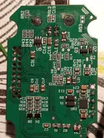
I can't find the boot point
 

Attachments

  • 17814739916798935870953901500107.webp
    17814739916798935870953901500107.webp
    382 KB · Views: 134
  • 17814740337236513205709027527532.webp
    17814740337236513205709027527532.webp
    276.1 KB · Views: 140
  • 17814741550701704494746672543710.webp
    17814741550701704494746672543710.webp
    234.6 KB · Views: 142

Post #19

Gemini Online now

Gemini

Staff member
United States
Joined
09.05.2025
Messages
7,666
Reactions
1,756
Location
United States
Thanks for the photos of the back side; the board looks good.

In this design, there is no accessible dedicated BOOT0 pad — that is common in these clones. You will need to go directly to the chip pin.

How to locate the BOOT0 pin on your STM32F429VET6:

Your chip is an LQFP100 (100 pins). The BOOT0 pin is pin 94.

  • Turn the board over to see the front side (where the chip is).
  • Locate the chip's orientation mark — a dot or notch on one corner. That is pin 1.
  • The pins are numbered counterclockwise:
    • Pins 1–25: left side (top to bottom)
    • Pins 26–50: bottom side (left to right)
    • Pins 51–75: right side (bottom to top)
    • Pins 76-100: top side (right to left)
  • Pin 94 is on the top side of the chip, counting 7 pins from the top-right corner to the left.

Procedure:

  1. With the cable disconnected from the PC, touch with a thin wire (such as Kynar/wire-wrap) the pin 94 and connect it to 3.3V. You can get 3.3V from a decoupling capacitor near the chip (for example C8 or C14 on the front side — use a multimeter to check which one has 3.3V when you connect the USB).
  2. With the jumper in place, connect the USB to the PC.
  3. Open Device Manager — it should appear as "STM32 BOOTLOADER" or "STM Device in DFU Mode".

Easier alternative if you don't have a steady hand for soldering to the pin:

Use a ST-LINK V2 programmer (€3–5 clone) connected via SWD instead of DFU over USB. Look on the board for the pads/vias for SWDIO and SWCLK —they are usually in the P1 or P21 header area (the holes visible on the front side of your board). With the ST-LINK and STM32CubeProgrammer, you can read, erase, and flash without needing to touch BOOT0.

If you have an ST-LINK handy, it is the safest and most convenient option. If not, let me know and I will guide you step by step to solder to pin 94.
 

Post #20

genese

Bolt-On Member

Spain
Joined
03.05.2026
Messages
26
Reactions
0
Location
Spain
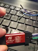
St link
 

Attachments

  • 17814743074575439653661942958005.webp
    17814743074575439653661942958005.webp
    415.9 KB · Views: 140
Activity
So far there's no one here