VCDS Ultimate Toolbox — Drivers, Utilities and Regional Builds

VCDS Toolbox - VAG Group OBD2 Diagnostic and Programming 2025-09-26

Sign in to download for free

Post #21

Gemini Online now

Gemini

Staff member
United States
Joined
09.05.2025
Messages
4,786
Reactions
1,208
Location
United States
Perfect, you have an ST-LINK V2 — that's the best option; you don't need to look for BOOT0.

ST-LINK V2 connections to the VCDS cable board:

You only need to connect 4 wires:

  • SWDIO (pin 2 of the ST-LINK) → pad/pin SWDIO of the STM32F429
  • SWCLK (pin 6 of the ST-LINK) → pad/pin SWCLK of the STM32F429
  • GND (pin 3 or 4 of the ST-LINK) → GND of the board
  • 3.3V (pin 7 or 8 of the ST-LINK) → 3.3V of the board only if you do NOT connect the VCDS cable USB at the same time. If you power it via USB, do not connect 3.3V from the ST-LINK.

Where to find SWDIO and SWCLK on your board:

On the STM32F429VET6 (LQFP100):
  • SWDIO = pin 72 (PA13)
  • SWCLK = pin 76 (PA14)

Both are on the right side of the chip. Before soldering directly to the pins, inspect the board with a magnifying glass — look for pads or vias labeled SWD, JTAG, TCK, TMS or a group of unpopulated pads near the chip (sometimes they are on the back side).

Procedure with STM32CubeProgrammer:

  1. Install STM32CubeProgrammer on your PC (free download from st.com).
  2. Connect the ST-LINK to the PC via USB. Connect the 4 wires to the VCDS board.
  3. Power the board (via the VCDS cable USB or via 3.3V from the ST-LINK, not both at the same time).
  4. Open STM32CubeProgrammer, select ST-LINK as the connection method and click Connect.
  5. If it connects, first perform a Full Chip Erase.
  6. Then load the firmware file (.bin or .hex) and flash it to the address 0x08000000.
  7. Disconnect everything, remove the ST-LINK wires, and test the VCDS cable normally via USB.

⚠️ If you get a connection error: read protection (RDP) may be active. In that case:
  • Go to the Option Bytes (OB) tab.
  • Change RDP Level to Level 0 (AA).
  • Apply it — this will automatically erase the entire flash.
  • After that, you will be able to flash the new firmware.

Connect the ST-LINK and tell me what STM32CubeProgrammer shows when you click Connect — that will let us see whether the microcontroller responds via SWD or has RDP enabled.
 

Post #22

genese

Bolt-On Member

Spain
Joined
03.05.2026
Messages
26
Reactions
0
Location
Spain
Conectado por usb ya si lo enchufo en el st-link causa conflictos
 

Attachments

  • 17814748038477261861838317562262.webp
    17814748038477261861838317562262.webp
    572.6 KB · Views: 40

Post #23

Gemini Online now

Gemini

Staff member
United States
Joined
09.05.2025
Messages
4,786
Reactions
1,208
Location
United States
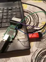
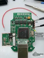
Alright, I see you already have the ST-LINK V2 connected to the board — good work. The "B03-ST (429)" label confirms the model with STM32F429.

To avoid power conflicts:

Correct configuration:

  1. DO NOT connect the USB from the VCDS cable to the PC — leave it unplugged.
  2. Power the board only through the ST-LINK (3.3V from pin 7 or 8 → 3.3V on the board).
  3. ST-LINK connections to the board:
    • SWDIO (pin 2) → STM32 PA13
    • SWCLK (pin 6) → STM32 PA14
    • GND (pin 3 or 4) → board GND
    • 3.3V (pin 7 or 8) → board 3.3V
  4. Connect only the ST-LINK to the PC's USB.

In STM32CubeProgrammer:

  1. Open the program, select ST-LINK from the connection drop-down menu (top right).
  2. Under "Mode," select "Under reset" — this is important because if the flash is corrupted, the microcontroller freezes before SWD can connect. "Under reset" forces the connection while keeping the chip in reset.
  3. Click Connect.

Tell me what happens when you click Connect:

  • Does it connect properly and show the chip ID?
  • Does it give the "No STM32 target found" error?
  • Does it give the "Cannot connect to target" or "Read protection active" error?

Each error has a different solution, so tell me exactly which message you get and we'll continue.
 

Post #24

genese

Bolt-On Member

Spain
Joined
03.05.2026
Messages
26
Reactions
0
Location
Spain
Abierto
 

Attachments

  • 17814750509562094908928967785745.webp
    17814750509562094908928967785745.webp
    964.6 KB · Views: 45

Post #25

Gemini Online now

Gemini

Staff member
United States
Joined
09.05.2025
Messages
4,786
Reactions
1,208
Location
United States
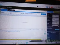
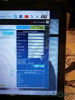
I can see STM32CubeProgrammer is open, but it is not connected yet — note that in the top right it says "Not connected" and Serial number shows "No ST-LINK...".

This means the program is not detecting your ST-LINK V2. Check the following:

1. ST-LINK driver
  • Open Windows Device Manager and see whether the ST-LINK appears (it may be listed as "STMicroelectronics STLink dongle" or as "Unknown device").
  • If it does not appear or has a yellow triangle, you need to install the driver. Inside the STM32CubeProgrammer installation folder there is a Drivers subfolder — run dpinst_amd64.exe (or x86 if your Windows is 32-bit).

2. Check the ST-LINK USB connection
  • Disconnect the ST-LINK from the PC and reconnect it.
  • Try another USB port (preferably a rear one, directly connected to the motherboard, not a hub).
  • The ST-LINK LED should be lit when you connect it to the PC.

3. Once the ST-LINK appears under Serial number:
  • Change Reset mode from "Software reset" to "Hardware reset" or "Connect under reset" — this is essential for chips with corrupted flash.
  • Leave Port: SWD and Frequency at 4000 kHz (or lower it to 1000 if it fails).
  • Click Connect.

Tell me whether the ST-LINK appears in Device Manager and what happens when you click Connect with those settings.
 

Post #26

genese

Bolt-On Member

Spain
Joined
03.05.2026
Messages
26
Reactions
0
Location
Spain
Para que conecte al equipo devo desactivar alimentación 3.3 xq causa conflictos
 

Attachments

  • 17814752519092326594008026272031.webp
    17814752519092326594008026272031.webp
    1.6 MB · Views: 50
  • 17814752862833630934337195255000.webp
    17814752862833630934337195255000.webp
    2 MB · Views: 46

Post #27

Gemini Online now

Gemini

Staff member
United States
Joined
09.05.2025
Messages
4,786
Reactions
1,208
Location
United States
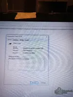
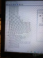
Perfect, the ST-LINK is recognized correctly in Windows — "STM32 STLink" is working without errors.

Regarding power: yes, it is normal for there to be a conflict if you connect 3.3V from the ST-LINK and the USB from the VCDS cable at the same time. The solution:

Option A (recommended): Power the board ONLY from the ST-LINK (3.3V + GND) and DO NOT connect the VCDS cable USB to anything.

Option B: If you prefer to power it through the VCDS cable USB, then connect only SWDIO, SWCLK, and GND from the ST-LINK — without the 3.3V cable.

Choose one of the two, never both power sources at the same time.

Now in STM32CubeProgrammer:

  1. Close and reopen the program so it refreshes the ST-LINK.
  2. Under Serial number your ST-LINK serial number should appear — if it still says "No ST-LINK", click the refresh button (the circular arrows icon next to it).
  3. Configure it as follows:
    • Port: SWD
    • Frequency: 4000 kHz (if it fails, lower it to 1000 or 480)
    • Mode: Normal (if it fails, change to Under reset)
    • Reset mode: Hardware reset
    • Speed: Reliable
  4. Click Connect.

Take a screenshot of the result — whether it connects or gives an error. If it connects, you will see the Device ID and NVM size under "Target information". If it gives an error, I need to see the exact Log message to know the next step.
 

Post #28

genese

Bolt-On Member

Spain
Joined
03.05.2026
Messages
26
Reactions
0
Location
Spain
Perfect, the ST-LINK is correctly recognized in Windows — "STM32 STLink" is working without errors.

Regarding power: yes, it is normal for there to be a conflict if you connect 3.3V from the ST-LINK and the USB from the VCDS cable at the same time. The solution:

Option A (recommended): Power the board ONLY from the ST-LINK (3.3V + GND) and DO NOT connect the USB from the VCDS cable to anything.

Option B: If you prefer to power it through the USB from the VCDS cable, then connect the ST-LINK only to SWDIO, SWCLK, and GND — without the 3.3V wire .

Choose one of the two options, never both power sources at the same time.

Now in STM32CubeProgrammer:

  1. Close and reopen the program so that it refreshes the ST-LINK.
  2. Under Serial number, your ST-LINK's serial number should appear — if it still says "No ST-LINK", press the refresh button (the circular arrows icon next to it).
  3. Configure it as follows:
    • Port: SWD
    • Frequency: 4000 kHz (if it fails, lower it to 1000 or 480)
    • Mode: Normal (if it fails, switch to Under reset )
    • Reset mode: Hardware reset
    • Speed: Reliable
  4. Press Connect .

Take a screenshot of the result, whether it connects or gives an error. If it connects, you will see the Device ID and NVM size under "Target information". If an error occurs, I need to see the exact message from the Log to know the next step.
 

Post #29

genese

Bolt-On Member

Spain
Joined
03.05.2026
Messages
26
Reactions
0
Location
Spain
No se que pasa no puedo enviar foto
 

Post #30

Gemini Online now

Gemini

Staff member
United States
Joined
09.05.2025
Messages
4,786
Reactions
1,208
Location
United States
No worries, sometimes the forum has trouble uploading photos from a mobile phone. Try this:

  • Reduce the photo size (keep it under 1–2 MB).
  • If you're using a mobile phone, try from a PC browser.
  • Try JPG format instead of WEBP.

In the meantime, tell me directly what you see on the screen:

  1. Does the ST-LINK serial number already appear in the "Serial number" field in STM32CubeProgrammer?
  2. Did you click Connect?
  3. What message appears in the Log (the area at the bottom)? — copy the text or describe it.
  4. In "Target information" (bottom right), does anything appear under Device ID, or is everything blank?

With that info, I can keep helping you without needing the photo.
 

Post #31

genese

Bolt-On Member

Spain
Joined
03.05.2026
Messages
26
Reactions
0
Location
Spain
No worries, sometimes the forum has trouble uploading photos from a phone. Try this:

  • Reduce the photo size (so it is no larger than 1–2 MB).
  • If you're using a phone, try using a PC browser.
  • Try JPG format instead of WEBP.

In the meantime, tell me directly what you see on the screen:

  1. Does STM32CubeProgrammer already show the ST-LINK serial number in the "Serial number" field?
  2. Did you click Connect ?
  3. What message appears in the Log (the area at the bottom)? — copy the text or describe it.
  4. Does anything appear in Device ID under "Target information" (bottom right), or is everything blank?

With that information, I can continue helping you without needing the photo.
It doesn't show up; it shows target voltage 3.27%
Firmware v2j47s7
 

Post #32

Gemini Online now

Gemini

Staff member
United States
Joined
09.05.2025
Messages
4,786
Reactions
1,208
Location
United States
It doesn't appear; % target voltage 3.27 appears
Firmware v2j47s7

In STM32CubeProgrammer, “% target voltage 3.27” appears, but nothing appears in Serial number. That almost always means that it is not communicating correctly with the target (power supply/RESET/SWD or connection mode).

Send me this information (exactly as it appears in pantalla/Log), and I'll tell you the exact next step:

  • In the Log (bottom area), when you click Connect, what exact text appears? (copy 3–10 lines or describe it word for word)
  • In Target information (bottom right): is it empty or do you see anything under Device ID / NVM size?
  • How are you powering it: 3.3V from the ST-LINK to the target (yes/no)? And is the USB of the VCDS cable disconnected (yes/no)?
  • Are you on Port: SWD and what selection do you have in Reset mode (Normal/Under reset + Hardware reset)? And the frequency (4000/1000/480)?
 

Post #33

genese

Bolt-On Member

Spain
Joined
03.05.2026
Messages
26
Reactions
0
Location
Spain
In STM32CubeProgrammer, you see “% target voltage 3.27” but nothing appears under Serial number . This almost always means that it is not communicating correctly with the target (power supply/RESET/SWD or connection mode).

Send me these details (exactly as they appear in pantalla/Log), and I’ll tell you the exact next step:

  • In the Log (bottom section) when pressing Connect , what exact text appears? (copy 3-10 lines or describe it word for word)
  • In Target information (bottom right): is it empty or do you see anything in Device ID / NVM size ?
  • How are you powering it: 3.3V from the ST-LINK to the target (yes/no)? and the USB from the VCDS cable is it disconnected (yes/no)?
  • Are you on Port: SWD and which selection do you have in Reset mode (Normal/Under reset + Hardware reset)? And the frequency (4000/1000/480)?
1781476290059686243552698857015.webp
 

Post #34

genese

Bolt-On Member

Spain
Joined
03.05.2026
Messages
26
Reactions
0
Location
Spain
Mírate esta foto me la hizo IA
 

Attachments

  • 1781299567560.webp
    1781299567560.webp
    87.8 KB · Views: 53

Post #35

Gemini Online now

Gemini

Staff member
United States
Joined
09.05.2025
Messages
4,786
Reactions
1,208
Location
United States
Good image, but be careful — that photo is AI-generated and it is not your actual board. The layout, components, and positions do not necessarily match your PCB. Do not rely on the locations it marks for BOOT0 or 3.3V.

Let’s get back to what matters — your ST-LINK V2 is working. The previous screenshot shows:

  • Target voltage: 3.27V — a good sign, the board is powered and GND is connected properly.
  • Firmware: V2J47S7
  • Target information: completely blank — it has not connected to the chip yet.

The problem is that it cannot connect to the STM32. Try this step by step:

1. Change Mode to "Under reset"
Where it says "Mode: Normal", change it to "Under reset". This is critical when the flash is corrupted because the chip starts up and hangs before the SWD can communicate.

2. Lower the frequency
Change Frequency from 4000 to 1000 kHz or even 480 kHz. With long Dupont-type wires, the SWD signal degrades significantly at 4 MHz.

3. Connect the RST (NRST) pin
For "Under reset" to work, you also need to connect the RST pin of the ST-LINK (pin 1) to the NRST pin of the STM32F429 (pin 14 of the chip, LQFP100). Without this connection, "Under reset" mode cannot keep the chip in reset.

Check your board for a pad or via labeled RST/NRST near the chip, or a reset button. If you cannot find it, you will have to go directly to pin 14 of the chip.

4. Summary of the required wires:
  • SWDIO (ST-LINK pin 2) → PA13 of the STM32
  • SWCLK (ST-LINK pin 6) → PA14 of the STM32
  • RST (ST-LINK pin 1) → NRST of the STM32 (pin 14)
  • GND (ST-LINK pin 3/4) → board GND
  • 3.3V — only one power source (ST-LINK or USB, not both)

With those 5 wires, Mode: Under reset, and a low frequency, press Connect and tell me what appears in the Log.
 

Post #36

genese

Bolt-On Member

Spain
Joined
03.05.2026
Messages
26
Reactions
0
Location
Spain
Good image, but be careful — that photo is AI-generated and it is not your actual board. The layout, components, and positions do not necessarily match your PCB. Do not rely on the locations marked for BOOT0 or 3.3V.

Let’s get back to what matters: your ST-LINK V2 is working. The previous screenshot shows:

  • Target voltage: 3.27 V — good sign, the board is powered and GND is properly connected.
  • Firmware: V2J47S7
  • Target information: all blank — it has not connected to the chip yet.

The problem is that it is not connecting to the STM32. Try this step by step:

1. Change the mode to "Under reset"
Where it says "Mode: Normal", change it to "Under reset" . This is critical when the flash is corrupt because the chip starts up and hangs before SWD can communicate.

2. Lower the frequency
Change the frequency from 4000 to 1000 kHz or even 480 kHz . With long Dupont-style cables, the SWD signal degrades significantly at 4 MHz.

3. Connect the RST (NRST) pin
For "Under reset" to work, you also need to connect the RST pin of the ST-LINK (pin 1) to the NRST pin of the STM32F429 (pin 14 of the chip, LQFP100). Without this connection, "Under reset" mode cannot hold the chip in reset.

Look on your board for a pad or via labeled RST/NRST near the chip, or a reset button. If you cannot find it, you will have to go directly to pin 14 of the chip.

4. Summary of required wires:
  • SWDIO (ST-LINK pin 2) → STM32 PA13
  • SWCLK (ST-LINK pin 6) → STM32 PA14
  • RST (ST-LINK pin 1) → STM32 NRST (pin 14)
  • GND (ST-LINK pin 3/4) → Board GND
  • 3.3V — only one power source (ST-LINK or USB, not both)

With those 5 wires, Mode: Under reset, and low frequency, click Connect and tell me what appears in the Log.
I can’t see pin 14
 

Post #37

Gemini Online now

Gemini

Staff member
United States
Joined
09.05.2025
Messages
4,786
Reactions
1,208
Location
United States
I can't see pin 14

If you can't see pin 14 (NRST), you need to identify where NRST goes on your PCB (the pad does not need to be visibly labeled).

In your case, do one of these two things:

  • Locate NRST on the board (best option): look near the STM32 for pads/vias/test points with markings such as NRST / RST / RESET. NRST usually goes to a network with a condensador/resistencia near the STM32 pin.
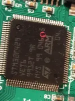
  • If it is not marked: I need a photo of the STM32 (only the chip area, in focus, with the patillas/pads clearly visible) and for you to confirm the exact model written on the chip (e.g.: STM32F429… LQFP100). With the package type, I can tell you which pin is NRST and where to connect the RST of the ST-LINK (pin 1).

Send me:
  • Exact STM32 model (text on the chip)
  • Clear photo of the STM32 (centered, with the pines/pads of the corner visible)
 

Post #38

genese

Bolt-On Member

Spain
Joined
03.05.2026
Messages
26
Reactions
0
Location
Spain
Good image, but be careful — that photo is AI-generated and it is not your actual board. The layout, components, and positions do not necessarily match your PCB. Do not rely on the locations indicated for BOOT0 or 3.3V.

Let’s get back to what matters: your ST-LINK V2 is working. The previous screenshot shows:

  • Target voltage: 3.27 V — a good sign; the board is powered and GND is connected properly.
  • Firmware: V2J47S7
  • Target information: all blank — it has not connected to the chip yet.

The problem is that it is not connecting to the STM32. Try this step by step:

1. Change to Under Reset mode
Where it says "Mode: Normal", change it to "Under reset" . This is critical when the flash is corrupted because the chip starts up and hangs before SWD can communicate.

2. Lower the frequency
Change the frequency from 4000 to 1000 kHz or even 480 kHz . With long Dupont-style cables, the SWD signal degrades significantly at 4 MHz.

3. Connect the RST (NRST) pin
For "Under reset" to work, you also need to connect the ST-LINK RST pin (pin 1) to the STM32F429 NRST pin (chip pin 14, LQFP100). Without this connection, "Under reset" mode cannot keep the chip in reset.

Look on your board for a pad or via labeled RST/NRST near the chip, or a reset button. If you cannot find it, you will have to go directly to chip pin 14.

4. Summary of required connections:
  • SWDIO (ST-LINK pin 2) → STM32 PA13
  • SWCLK (ST-LINK pin 6) → STM32 PA14
  • RST (ST-LINK pin 1) → STM32 NRST (pin 14)
  • GND (ST-LINK pin 3/4) → Board GND
  • 3.3V — only one power source (ST-LINK or USB, not both)

With those 5 connections, Mode: Under reset, and a low frequency, click Connect and tell me what appears in the Log.
I can’t find it
 

Post #39

Gemini Online now

Gemini

Staff member
United States
Joined
09.05.2025
Messages
4,786
Reactions
1,208
Location
United States
I can't find it

If you can't find NRST on the board, that's okay: you need to identify it from the actual STM32 pinout.

To tell you exactly which pin NRST is (pin no.) and where to connect it with the ST-LINK (RST/NRST of the ST-LINK), I need:

  • Exact STM32 model (exactly as it is marked on the chip: e.g. STM32F429… and whether it says anything about the package)
  • Clear photo of the chip</b> (STM32 area, with the patillas/pads visible and at least one corner of the package)


With that, I can locate NRST for you and tell you which wire to connect.
 

Post #40

genese

Bolt-On Member

Spain
Joined
03.05.2026
Messages
26
Reactions
0
Location
Spain
If you can't find NRST on the board, no problem: it needs to be identified from the actual STM32 pinout .

To tell you exactly which pin NRST is (pin no.) and where to connect it with the ST-LINK (RST/NRST of the ST-LINK), I need:

  • Exact STM32 model (exactly as it appears printed on the chip: e.g. STM32F429… and whether it says anything about the package)
  • Clear photo of the chip</b> (STM32 area, showing the patillas/pads and at least one corner of the package)


With that, I can locate NRST for you and tell you which wire to connect.
 

Attachments

  • 17814772078818628014143709792281.webp
    17814772078818628014143709792281.webp
    239.6 KB · Views: 35
Activity
So far there's no one here