Post #21
 Online now
- Joined
- 09.05.2025
- Messages
- 4,788
- Reactions
- 1,208
- Location
- 🇺🇸USUnited States
Perfect, you have an ST-LINK V2 — that's the best option; you don't need to look for BOOT0.
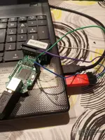
ST-LINK V2 connections to the VCDS cable board:
You only need to connect 4 wires:
Where to find SWDIO and SWCLK on your board:
On the STM32F429VET6 (LQFP100):
Both are on the right side of the chip. Before soldering directly to the pins, inspect the board with a magnifying glass — look for pads or vias labeled SWD, JTAG, TCK, TMS or a group of unpopulated pads near the chip (sometimes they are on the back side).
Procedure with STM32CubeProgrammer:
 If you get a connection error: read protection (RDP) may be active. In that case:
Connect the ST-LINK and tell me what STM32CubeProgrammer shows when you click Connect — that will let us see whether the microcontroller responds via SWD or has RDP enabled.
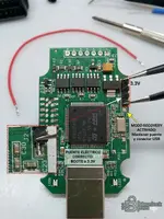
ST-LINK V2 connections to the VCDS cable board:
You only need to connect 4 wires:
- SWDIO (pin 2 of the ST-LINK) → pad/pin SWDIO of the STM32F429
- SWCLK (pin 6 of the ST-LINK) → pad/pin SWCLK of the STM32F429
- GND (pin 3 or 4 of the ST-LINK) → GND of the board
- 3.3V (pin 7 or 8 of the ST-LINK) → 3.3V of the board only if you do NOT connect the VCDS cable USB at the same time. If you power it via USB, do not connect 3.3V from the ST-LINK.
Where to find SWDIO and SWCLK on your board:
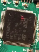
On the STM32F429VET6 (LQFP100):
- SWDIO = pin 72 (PA13)
- SWCLK = pin 76 (PA14)
Both are on the right side of the chip. Before soldering directly to the pins, inspect the board with a magnifying glass — look for pads or vias labeled SWD, JTAG, TCK, TMS or a group of unpopulated pads near the chip (sometimes they are on the back side).
Procedure with STM32CubeProgrammer:
- Install STM32CubeProgrammer on your PC (free download from st.com).
- Connect the ST-LINK to the PC via USB. Connect the 4 wires to the VCDS board.
- Power the board (via the VCDS cable USB or via 3.3V from the ST-LINK, not both at the same time).
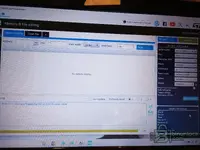
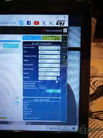
- Open STM32CubeProgrammer, select ST-LINK as the connection method and click Connect.
- If it connects, first perform a Full Chip Erase.
- Then load the firmware file (.bin or .hex) and flash it to the address 0x08000000.
- Disconnect everything, remove the ST-LINK wires, and test the VCDS cable normally via USB.
If you get a connection error: read protection (RDP) may be active. In that case:- Go to the Option Bytes (OB) tab.
- Change RDP Level to Level 0 (AA).
- Apply it — this will automatically erase the entire flash.
- After that, you will be able to flash the new firmware.
Connect the ST-LINK and tell me what STM32CubeProgrammer shows when you click Connect — that will let us see whether the microcontroller responds via SWD or has RDP enabled.