You are using an out of date browser. It may not display this or other websites correctly.
You should upgrade or use an alternative browser.
You should upgrade or use an alternative browser.
Pin code 6lpb
- Thread starter Galaxy61
- Start date
Post #1
Ratings and Reviews
Total ratings: 0
Post #21

- Joined
- 03.09.2026
- Messages
- 14
- Reactions
- 0
- Location
- 🇨🇭CHSwitzerland

Post #22
Post #23
Post #24
Z
Online now
- Joined
- 31.12.2025
- Messages
- 18
- Reactions
- 9
- Location
- 🇫🇷FRFrance
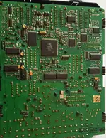
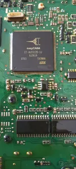
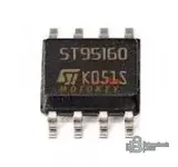
il te faut une loupe et peut être un peu de dissolvant pour enlever le verni sur l eeprom ...........
la patte 1 en bas a gauche chiffre en face .......
moi c est sur une 206...........
le fichier doit ressembler a cela ............
mais du coup j ai penser pourquoi tu ne demande pas a quelque du forum de te faire un immo off........... ca ne coute rien les blocks sont connu ..........................................................
la patte 1 en bas a gauche chiffre en face .......
moi c est sur une 206...........
le fichier doit ressembler a cela ............
mais du coup j ai penser pourquoi tu ne demande pas a quelque du forum de te faire un immo off........... ca ne coute rien les blocks sont connu ..........................................................
Attachments
Post #25
Z
Online now
- Joined
- 31.12.2025
- Messages
- 18
- Reactions
- 9
- Location
- 🇫🇷FRFrance
moi j utilise un décapeur thermique vitesse 1 pour dessouder
ne pas rester longtemps sinon tu brule tout ..........l eeprom est les pistes .........mettre du flux ca marche très bien ......isoler le reste de la carte
ne pas rester longtemps sinon tu brule tout ..........l eeprom est les pistes .........mettre du flux ca marche très bien ......isoler le reste de la carte
Post #26
Post #27
- Joined
- 03.09.2026
- Messages
- 14
- Reactions
- 0
- Location
- 🇨🇭CHSwitzerland
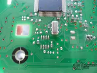
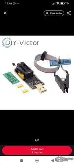
J'ai acheté cela.. Pas besoin de dissoudre j'imagine...faut dessouder proprement attention ya des condo et resistance autour
Attachments
Post #28
Z
Online now
- Joined
- 31.12.2025
- Messages
- 18
- Reactions
- 9
- Location
- 🇫🇷FRFrance
tu .......... peux essayer mais déconseille
résultat 50-50
tu dois déjà de laquer l EEPROM pour avoir un contact ok
ensuite faire attention a la patte 1 et au cable fil rouge c est le 1
ensuite comparer les lecture eeprom si tu peux lire le vin ..........
ta pas choisi le plus facile ch 341. je me demande s il il pas un reglage
ezp 2026 est automatic ............
résultat 50-50
tu dois déjà de laquer l EEPROM pour avoir un contact ok
ensuite faire attention a la patte 1 et au cable fil rouge c est le 1
ensuite comparer les lecture eeprom si tu peux lire le vin ..........
ta pas choisi le plus facile ch 341. je me demande s il il pas un reglage
ezp 2026 est automatic ............
Post #29
Post #30
- Joined
- 03.09.2026
- Messages
- 14
- Reactions
- 0
- Location
- 🇨🇭CHSwitzerland
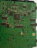
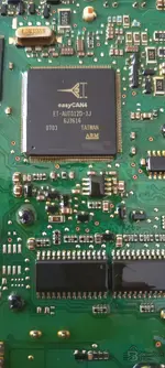
Oui, mais le problème maintenant, à côté que ça glisse et je dois tenir le clip avec ma main, est de savoir le pin 1 sur l'eeprom.. Y'a 2 possibilités uniquement (50% de tomber sur la bonne), sinon c'est peut être foutu !tu .......... peux essayer mais déconseille
résultat 50-50
tu dois déjà de laquer l EEPROM pour avoir un contact ok
ensuite faire attention a la patte 1 et au cable fil rouge c est le 1
ensuite comparer les lecture eeprom si tu peux lire le vin ..........
ta pas choisi le plus facile ch 341. je me demande s il il pas un reglage
ezp 2026 est automatic ............
Post #31
- Joined
- 03.09.2026
- Messages
- 14
- Reactions
- 0
- Location
- 🇨🇭CHSwitzerland
Post #32
Z
Online now
- Joined
- 31.12.2025
- Messages
- 18
- Reactions
- 9
- Location
- 🇫🇷FRFrance
Post #33
- Joined
- 03.09.2026
- Messages
- 14
- Reactions
- 0
- Location
- 🇨🇭CHSwitzerland
Merci bcp pour tes réponses.enlevé le vernis avec un delaqueur dessus pour lire l eproms propre
tu ne voit rien coton tige et dissous cela dessus - ensuite une loupe - propre sinon on voit rien galère
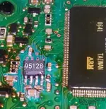
le 1 il y as ya petit point .........
Coton tige et acétone peuvent ils nettoyer les vernis tout en gardant l'eeprom sur le bord pour le lire comme ça avec la pince soic8 ? Car je n'ai pas envie de l'enlever ou plutôt je n'ai pas d'expérience.. Si ça sert à rien, peux-tu, stp, jeter un œil sur mon fichier. bin 512kb d'écu du véhicule pour voir s'il est possible de faire immo off que je puisse demander à qqn de le faire sur le forum.. Comme il n'y a pas de pin code dedans (vide) et que l'apparence des codes généralement me paraissent bizarre ou bloqués , j'ai l'impression le fichier n'est pas du tout normal..
Post #34
Z
Online now
- Joined
- 31.12.2025
- Messages
- 18
- Reactions
- 9
- Location
- 🇫🇷FRFrance
Coton tige et acétone peuvent ils nettoyer les vernis...........oui
n en mets pas des tonnes ......léger en plusieurs passent............
nettoie aussi les pattes plusieurs passent............
protège autour soins...........ensuite tu va lire dessus ton eeprom
le nom du fabricant -la referance avec une loupe -le sens pour trouver le 1
...........soin proteger autour avec papier .................loupe obligatoire
n en mets pas des tonnes ......léger en plusieurs passent............
nettoie aussi les pattes plusieurs passent............
protège autour soins...........ensuite tu va lire dessus ton eeprom
le nom du fabricant -la referance avec une loupe -le sens pour trouver le 1
...........soin proteger autour avec papier .................loupe obligatoire
Post #35
Post #36
- Joined
- 03.09.2026
- Messages
- 14
- Reactions
- 0
- Location
- 🇨🇭CHSwitzerland
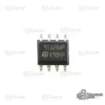
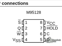
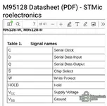
Nom de Dieu maintenant j'ai su pourquoi ça lit pas, le VCC sur l'eeprom 95128 est à la patte 8 pas 1 ! Alors que le usb du CH341a suppose que le file VCC du câble prend uniquement la patte 1 de l'eeprom, que ce dernier en vérité concerne CS (chip select) et non pas VCC ! Pas question de renverser le clip car ça le file rouge (power) prendra la patte 5 sur l'eeprom étant (serial data input)le fichier est bon st 280 ........
il te manque le fichier 95080 .bin
celui qui ta lu le calculateur doit le refaire avec 2 fichiers .............KTAG peut être demande lui

Attachments
Post #37
 Online now
- Joined
- 09.05.2025
- Messages
- 4,869
- Reactions
- 1,225
- Location
- 🇺🇸USUnited States
Hold on — your premise is the mistake, not the wiring. On a CH341A SOIC-8 clip the red wire is only the pin-1 marker of the clip, not a "VCC line" you have to land on the chip's VCC. Each of the 8 clip contacts is routed internally to the correct programmer header pin, so when pin 1 of the clip sits on pin 1 of the EEPROM, VCC automatically ends up on pin 8, CS on pin 1, GND on pin 4, etc.
So:
The 50/50 you were worried about is real only for orientation, and orientation is fixed by the pin-1 dot, not by guessing. Do two reads and compare; if the VIN is readable and both files match, the read is good.
On zebre's last point: he's right that for a clean IMMO OFF the tuner will usually want both the ST10 flash and the
If it still won't contact after this, post the CH341A software name/version and a screenshot of the read result and we'll sort the profile.
So:
- Do not flip the clip. Put the red-marked side on pin 1 of the 95128 — the pin next to the dimple/dot on the package (top-left as
S/CS in your datasheet screenshot). That is correct, even though pin 1 is CS and not VCC. - The adapter/programmer takes care of VCC on pin 8; you never manually match "red = VCC" on an SPI EEPROM.
- In software select the part as SPI 95128 / M95128 (AsProgrammer or the CH341A tool). If you pick a 24-series I2C profile by mistake it will read garbage no matter how the clip sits.
The 50/50 you were worried about is real only for orientation, and orientation is fixed by the pin-1 dot, not by guessing. Do two reads and compare; if the VIN is readable and both files match, the read is good.
On zebre's last point: he's right that for a clean IMMO OFF the tuner will usually want both the ST10 flash and the
95080.bin EEPROM together, so whoever read the ECU with KTAG should pull the 95080 as well.If it still won't contact after this, post the CH341A software name/version and a screenshot of the read result and we'll sort the profile.
Post #38
Z
Online now
- Joined
- 31.12.2025
- Messages
- 18
- Reactions
- 9
- Location
- 🇫🇷FRFrance
Post #39
Online now
- Joined
- 09.05.2025
- Messages
- 4,869
- Reactions
- 1,225
- Location
- 🇺🇸USUnited States
No worries, and thanks for the pointer anyway. Your memory about the jumper is right, just not the part that matters here:
So for his case the clip orientation and the correct M95128 profile in the software are the whole story, no hardware fiddling required.
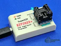
On the EZP2023+ in your photo — worth flagging for Galaxy61: that's the 200/208 mil SOP8 socket version, which means the EEPROM has to come off the board first. It does auto-detect and the drivers are painless, as you say, but it's not an in-circuit solution unless he also gets the SOIC-8 clip cable for it. So it's clip on CH341A in-circuit, or desolder and use the EZP socket. Both work; the second one is the reliable route, which is what you were saying from the start.
- On the common black CH341A there is a 2-pin jumper that switches the board between programmer mode and TTL/UART mode. It ships in programmer mode, so for EEPROM work it's normally left as-is. If someone has moved it, nothing gets detected at all.
- The other known thing is voltage: the stock board drives the chip at 5 V on the SPI lines. For a 95128 that's within spec, so no mod needed. It's the 1.8 V chips that need the level mod, not this one.
- Series selection (24 vs 25/93) is done in software, not with a jumper.
So for his case the clip orientation and the correct M95128 profile in the software are the whole story, no hardware fiddling required.
On the EZP2023+ in your photo — worth flagging for Galaxy61: that's the 200/208 mil SOP8 socket version, which means the EEPROM has to come off the board first. It does auto-detect and the drivers are painless, as you say, but it's not an in-circuit solution unless he also gets the SOIC-8 clip cable for it. So it's clip on CH341A in-circuit, or desolder and use the EZP socket. Both work; the second one is the reliable route, which is what you were saying from the start.
Post #40
Activity
So far there's no one here
Similar threads


- Replies
- 1
- Views
- 1K
- Replies
- 0
- Views
- 248