You are using an out of date browser. It may not display this or other websites correctly.
You should upgrade or use an alternative browser.
You should upgrade or use an alternative browser.
Pin code 6lpb
- Thread starter Galaxy61
- Start date
Post #1
Ratings and Reviews
Total ratings: 0
Post #21

- Joined
- 03.09.2026
- Messages
- 14
- Reactions
- 0
- Location
- 🇨🇭
 CHSwitzerland

Post #22
Post #23
Post #24

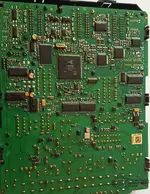
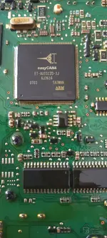
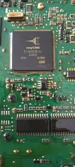
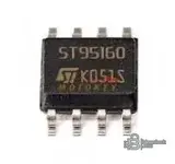
You need a magnifying glass and perhaps a little solvent to remove the varnish from the EEPROM...........
pin 1 is at the bottom left, with the number facing you.......
mine is on a 206...........
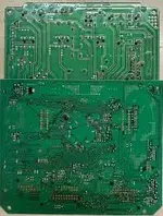
the file should look like this............
but then I thought, why don't you ask someone on the forum to make you a immo off........... it costs nothing, the blocks are known..........................................................
pin 1 is at the bottom left, with the number facing you.......
mine is on a 206...........
the file should look like this............
but then I thought, why don't you ask someone on the forum to make you a immo off........... it costs nothing, the blocks are known..........................................................
Attachments
Post #25
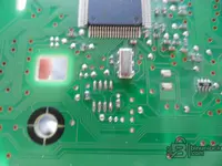
I use a heat gun at speed 1 for desoldering.
Don't stay in one spot too long, otherwise you'll burn everything—the EEPROM and the traces. Apply some flux; it works very well. Insulate the rest of the board.
Don't stay in one spot too long, otherwise you'll burn everything—the EEPROM and the traces. Apply some flux; it works very well. Insulate the rest of the board.
Post #26
Post #27
- Joined
- 03.09.2026
- Messages
- 14
- Reactions
- 0
- Location
- 🇨🇭CHSwitzerland
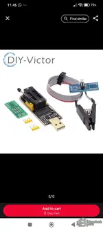
I bought this.. I assume no desoldering is needed...You have to desolder it cleanly; be careful, there are capacitors and resistors around it
Attachments
Post #28
You can try .......... but I don't recommend it
The odds are 50-50
First, you need to remove the lacquer from the EEPROM to get proper contact
Then pay attention to pin 1 and the red cable wire, that's pin 1
Then compare the EEPROM readings; if you can read the VIN ..........
You didn't choose the easiest one, CH341. I wonder if there is a setting
EZP 2026 is automatic ............
The odds are 50-50
First, you need to remove the lacquer from the EEPROM to get proper contact
Then pay attention to pin 1 and the red cable wire, that's pin 1
Then compare the EEPROM readings; if you can read the VIN ..........
You didn't choose the easiest one, CH341. I wonder if there is a setting
EZP 2026 is automatic ............
Post #29
Post #30
- Joined
- 03.09.2026
- Messages
- 14
- Reactions
- 0
- Location
- 🇨🇭CHSwitzerland
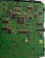
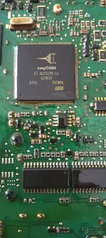
Yes, but the problem now, besides it slipping and me having to hold the clip with my hand, is figuring out pin 1 on the EEPROM... There are only 2 possibilities (a 50% chance of getting the right one); otherwise it may be ruined!you .......... you can try, but I don't recommend it
50-50 result
you must first sand the EEPROM to get a good contact
then pay attention to pin 1 and the red wire of the cable; that's pin 1
then compare the EEPROM readings; if you can read the VIN ..........
you didn't choose the easiest one, CH341. I wonder whether there is a setting
EZP 2026 is automatic ............
Post #31
- Joined
- 03.09.2026
- Messages
- 14
- Reactions
- 0
- Location
- 🇨🇭CHSwitzerland
Post #32
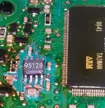
I removed the varnish with stripper on top so I could read the EEPROMs properly.
You can't see anything. Use a cotton swab and dissolve it on top, then use a magnifying glass. Clean it properly, otherwise you can't see anything; it's a real hassle.
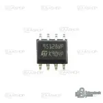
Pin 1 has a small dot.........
You can't see anything. Use a cotton swab and dissolve it on top, then use a magnifying glass. Clean it properly, otherwise you can't see anything; it's a real hassle.
Pin 1 has a small dot.........
Attachments
Post #33
- Joined
- 03.09.2026
- Messages
- 14
- Reactions
- 0
- Location
- 🇨🇭CHSwitzerland
Thank you very much for your replies.Remove the coating on top with a paint stripper so that you can clearly read the EPROM.
You can't see anything—apply the solvent with a cotton swab, then use a magnifying glass. Clean it well, otherwise you won't be able to see anything; it's a pain.
Pin 1 has a small dot.........
Can a cotton swab and acetone remove the coating while leaving the EEPROM on the board so that I can read it with the SOIC8 clip? I don't want to remove it, or rather, I don't have the experience. If that is pointless, could you please take a look at my 512kb vehicle ECU .bin file to see whether it is possible to do immo off so that I can ask someone on the forum to do it? Since there is no PIN code in it (it is empty) and the code patterns generally seem strange or blocked to me, I have the impression that the file is not normal at all.
Post #34
Can cotton swabs and acetone remove the lacquer?...........yes
Don't use too much ......apply lightly in several passes............
Clean the pins in several passes too............
Carefully protect the surrounding area...........then you'll read the details on your EEPROM:
the manufacturer's name, the part number with a magnifying glass, and the orientation to find pin 1
...........carefully protect the surrounding area with paper .................a magnifying glass is essential
Don't use too much ......apply lightly in several passes............
Clean the pins in several passes too............
Carefully protect the surrounding area...........then you'll read the details on your EEPROM:
the manufacturer's name, the part number with a magnifying glass, and the orientation to find pin 1
...........carefully protect the surrounding area with paper .................a magnifying glass is essential
Post #35
Post #36
- Joined
- 03.09.2026
- Messages
- 14
- Reactions
- 0
- Location
- 🇨🇭CHSwitzerland
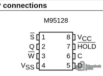
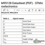
Good grief, now I know why it doesn't read: the VCC on the 95128 EEPROM is on pin 8, not 1! Whereas the CH341a USB assumes that the VCC wire of the cable connects only to pin 1 of the EEPROM, which actually corresponds to CS (chip select) and not VCC! No way to reverse the clip, because then the red (power) wire would connect to pin 5 on the EEPROM, which is (serial data input)the file is good st 280 ........
il te manque le fichier 95080 .bin
the person who read the ECU for you must do it again with 2 files .............KTAG maybe ask him

Attachments
Post #37
 Online now
- Joined
- 09.05.2025
- Messages
- 7,308
- Reactions
- 1,685
- Location
- 🇺🇸
 USUnited States
Hold on — your premise is the mistake, not the wiring. On a CH341A SOIC-8 clip the red wire is only the pin-1 marker of the clip, not a "VCC line" you have to land on the chip's VCC. Each of the 8 clip contacts is routed internally to the correct programmer header pin, so when pin 1 of the clip sits on pin 1 of the EEPROM, VCC automatically ends up on pin 8, CS on pin 1, GND on pin 4, etc.
So:
The 50/50 you were worried about is real only for orientation, and orientation is fixed by the pin-1 dot, not by guessing. Do two reads and compare; if the VIN is readable and both files match, the read is good.
On zebre's last point: he's right that for a clean IMMO OFF the tuner will usually want both the ST10 flash and the
If it still won't contact after this, post the CH341A software name/version and a screenshot of the read result and we'll sort the profile.
So:
- Do not flip the clip. Put the red-marked side on pin 1 of the 95128 — the pin next to the dimple/dot on the package (top-left as
S/CS in your datasheet screenshot). That is correct, even though pin 1 is CS and not VCC. - The adapter/programmer takes care of VCC on pin 8; you never manually match "red = VCC" on an SPI EEPROM.
- In software select the part as SPI 95128 / M95128 (AsProgrammer or the CH341A tool). If you pick a 24-series I2C profile by mistake it will read garbage no matter how the clip sits.
The 50/50 you were worried about is real only for orientation, and orientation is fixed by the pin-1 dot, not by guessing. Do two reads and compare; if the VIN is readable and both files match, the read is good.
On zebre's last point: he's right that for a clean IMMO OFF the tuner will usually want both the ST10 flash and the
95080.bin EEPROM together, so whoever read the ECU with KTAG should pull the 95080 as well.If it still won't contact after this, post the CH341A software name/version and a screenshot of the read result and we'll sort the profile.
Post #38
hello ... I can't help you with that, I don't know the CH 341......
there are some operations to perform ......... regarding the jumpers, I have heard about them, but.........
that's why I recommended EZP to you; it's automatic ....... I know how it works and I know the drivers
there are some operations to perform ......... regarding the jumpers, I have heard about them, but.........
that's why I recommended EZP to you; it's automatic ....... I know how it works and I know the drivers
Attachments
Post #39
Online now
- Joined
- 09.05.2025
- Messages
- 7,308
- Reactions
- 1,685
- Location
- 🇺🇸USUnited States
No worries, and thanks for the pointer anyway. Your memory about the jumper is right, just not the part that matters here:
So for his case the clip orientation and the correct M95128 profile in the software are the whole story, no hardware fiddling required.
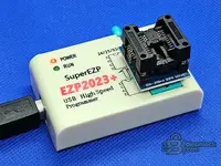
On the EZP2023+ in your photo — worth flagging for Galaxy61: that's the 200/208 mil SOP8 socket version, which means the EEPROM has to come off the board first. It does auto-detect and the drivers are painless, as you say, but it's not an in-circuit solution unless he also gets the SOIC-8 clip cable for it. So it's clip on CH341A in-circuit, or desolder and use the EZP socket. Both work; the second one is the reliable route, which is what you were saying from the start.
- On the common black CH341A there is a 2-pin jumper that switches the board between programmer mode and TTL/UART mode. It ships in programmer mode, so for EEPROM work it's normally left as-is. If someone has moved it, nothing gets detected at all.
- The other known thing is voltage: the stock board drives the chip at 5 V on the SPI lines. For a 95128 that's within spec, so no mod needed. It's the 1.8 V chips that need the level mod, not this one.
- Series selection (24 vs 25/93) is done in software, not with a jumper.
So for his case the clip orientation and the correct M95128 profile in the software are the whole story, no hardware fiddling required.
On the EZP2023+ in your photo — worth flagging for Galaxy61: that's the 200/208 mil SOP8 socket version, which means the EEPROM has to come off the board first. It does auto-detect and the drivers are painless, as you say, but it's not an in-circuit solution unless he also gets the SOIC-8 clip cable for it. So it's clip on CH341A in-circuit, or desolder and use the EZP socket. Both work; the second one is the reliable route, which is what you were saying from the start.
Post #40
Activity
So far there's no one here
Similar threads

- Replies
- 0
- Views
- 100


- Replies
- 1
- Views
- 1K