
Automotive Mechatronics Fundamentals is a substantial training PDF for technicians beginning electronic control-module diagnosis and repair across cars and trucks. The book is positioned as the first part of an ECM repair curriculum and provides a bridge between basic electronics, vehicle systems and practical module work.
Use it to establish vocabulary and test discipline before attempting board repair. A training book cannot identify every ECU pin, component value or software dependency; the exact controller still requires a verified schematic or pinout, datasheets, current-limited power and a known-good reference.
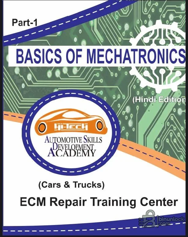
The book is appropriate for automotive electricians, diagnostic technicians, electronics repair trainees and workshop staff moving from scan-tool work toward circuit analysis. The cover identifies a Hindi edition; diagrams and technical terms may still use international component abbreviations. Readers should be prepared to translate terminology carefully rather than guessing.
Before opening a controller, document its Bosch, Continental, Denso, Delphi, Marelli, Siemens or OEM identity, photograph the board and establish whether the case can be opened without damaging the substrate. Confirm whether the fault is actually inside the ECU; wiring, grounds, power distribution, sensors and actuators can create identical symptoms.
Practice on non-customer hardware, use ventilation and eye protection for solder work, and follow ESD controls. For any repair affecting engine safety, braking, restraint or emissions operation, perform the manufacturer’s verification procedure and keep a record of the work.
Use it to establish vocabulary and test discipline before attempting board repair. A training book cannot identify every ECU pin, component value or software dependency; the exact controller still requires a verified schematic or pinout, datasheets, current-limited power and a known-good reference.
Training focus#
- Automotive mechatronics and electronic-control fundamentals
- Cars and truck ECM repair context
- Electronic components and their function in vehicle modules
- Measurement and diagnostic reasoning
- Relationship between sensors, processors and actuators
- Foundation for later board-level repair practice
Who this book is for#
The book is appropriate for automotive electricians, diagnostic technicians, electronics repair trainees and workshop staff moving from scan-tool work toward circuit analysis. The cover identifies a Hindi edition; diagrams and technical terms may still use international component abbreviations. Readers should be prepared to translate terminology carefully rather than guessing.
Tools for practical study#
- Digital multimeter with protected automotive inputs
- Current-limited bench power supply
- ESD mat and wrist protection
- Oscilloscope for signal work after fundamentals are understood
- Magnification and adequate lighting
- Datasheets and a verified ECU pinout
- Known spare module for training instead of a customer controller
Recommended learning workflow#
- Review voltage, current, resistance and power before working on a module.
- Identify common resistors, capacitors, diodes, transistors, regulators and drivers.
- Trace the ECU power path from connector to protection and regulation stages.
- Study sensor inputs and actuator outputs as separate signal chains.
- Measure a known spare board unpowered first, then under current-limited supply.
- Record expected and measured values and use differences to form a testable diagnosis.
ECU repair preparation#
Before opening a controller, document its Bosch, Continental, Denso, Delphi, Marelli, Siemens or OEM identity, photograph the board and establish whether the case can be opened without damaging the substrate. Confirm whether the fault is actually inside the ECU; wiring, grounds, power distribution, sensors and actuators can create identical symptoms.
Compatibility and scope limits#
- General electronics principles apply broadly, but board layouts do not
- Controller part number and hardware revision must match any reference
- Hybrid, ceramic and multilayer modules need specialized techniques
- Safety, restraint, braking and high-voltage controllers require additional controls
- The book does not replace current service information or calibration software
- Component replacement alone may not solve corrupt firmware or coding
Common beginner errors#
- Applying power without a verified pinout
- Using continuity mode on a live circuit
- Replacing a visibly damaged component without finding the cause
- Overheating multilayer boards or lifting pads
- Assuming all grounds are equivalent
- Programming memory before preserving an original read
- Testing on a customer vehicle before bench verification
System requirements and reading#
- Any desktop system with a current PDF reader
- Enough screen resolution to inspect diagrams and photographs
- Local storage for the original PDF and personal notes
- Optional translation tools for the edition language
- No installer, driver or internet connection is required
Safety and professional boundaries#
Practice on non-customer hardware, use ventilation and eye protection for solder work, and follow ESD controls. For any repair affecting engine safety, braking, restraint or emissions operation, perform the manufacturer’s verification procedure and keep a record of the work.


