
ECU Repair Training Manuals is an eight-document PDF library covering automotive module diagnosis, electronics, wiring interpretation and introductory repair workflows. It combines two repair-manual volumes with diagnostic basics, a structured module-diagnosis guide, a broader electronics text, multi-brand electrical diagrams and immobilizer reset or decoding theory.
The documents are educational references, not a guaranteed repair recipe for every controller. Use them to build a repeatable diagnostic process, then match every pinout, component and memory operation to the exact ECU manufacturer, part number, hardware revision and vehicle application.
The library contains material in more than one language, including English, Portuguese and Spanish titles or sections. All content is supplied as standard PDF files, so no automotive executable or installer is required. Use a modern reader with search, bookmarks and page rotation, and translate technical terms carefully.
The multi-brand diagrams and examples can help with common Bosch, Continental, Delphi, Denso, Marelli, Siemens and OEM module concepts, but the library does not provide an exhaustive supported-ECU list. Two units with similar housings can use different processors, memories, pinouts and power stages. Select by exact identity, not by vehicle badge or connector shape.
The immobilizer document is included for authorized repair education, synchronization and replacement-module context. It is not permission to bypass vehicle security. Verify ownership, protect keys and PIN data, and use approved tools and procedures. Do not publish customer dumps, transponder data, secret keys or full VINs.
The documents are educational references, not a guaranteed repair recipe for every controller. Use them to build a repeatable diagnostic process, then match every pinout, component and memory operation to the exact ECU manufacturer, part number, hardware revision and vehicle application.
Verified documents included#
- Diagnostic Basics, ECU
- Electrical Diagrams for Multiple Brands
- How to Diagnose an Automotive ECU in Eight Steps
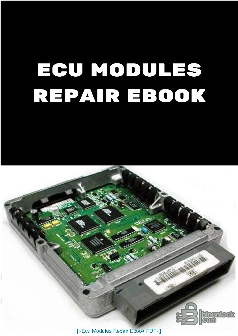
- ECU Modules Repair E-book
- ECU Repair Manual, first volume
- ECU Repair Manual, second volume
- Immobilizer Reset and Decode reference
- Technical Electronic Material
Learning scope#
- Diagnostic sequence before opening a control unit
- Electronic component and circuit fundamentals
- Power supply, ground, input and output-stage reasoning
- Reading automotive electrical diagrams
- Board-level inspection and measurement concepts
- Memory and immobilizer service context
- Repair documentation and verification
Language and document format#
The library contains material in more than one language, including English, Portuguese and Spanish titles or sections. All content is supplied as standard PDF files, so no automotive executable or installer is required. Use a modern reader with search, bookmarks and page rotation, and translate technical terms carefully.
Required bench equipment#
- Current-limited DC power supply
- Protected digital multimeter
- Oscilloscope for clock, communication and driver signals
- ESD-safe work area and magnification
- Temperature-controlled soldering and hot-air equipment for trained users
- Verified pinout, schematic or known-good reference
- Programmer appropriate for the exact memory device when memory work is required
Recommended module-diagnosis workflow#
- Confirm the vehicle complaint with a complete scan and power/ground checks.
- Record the ECU manufacturer, all part numbers, hardware revision and software identity.
- Inspect connectors, harness load behavior and related sensors or actuators before condemning the module.
- Preserve original flash and EEPROM data when a read is technically and legally appropriate.
- Use the manuals to plan non-destructive board measurements from supply input to processing and outputs.
- Repair only the proven failure, then bench-test under current limit.
- Reinstall, code or adapt as required and complete the manufacturer verification procedure.
Controller and vehicle compatibility#
The multi-brand diagrams and examples can help with common Bosch, Continental, Delphi, Denso, Marelli, Siemens and OEM module concepts, but the library does not provide an exhaustive supported-ECU list. Two units with similar housings can use different processors, memories, pinouts and power stages. Select by exact identity, not by vehicle badge or connector shape.
Immobilizer material and lawful use#
The immobilizer document is included for authorized repair education, synchronization and replacement-module context. It is not permission to bypass vehicle security. Verify ownership, protect keys and PIN data, and use approved tools and procedures. Do not publish customer dumps, transponder data, secret keys or full VINs.
Common diagnostic mistakes to avoid#
- Powering an ECU from an unverified pinout
- Assuming a communication fault proves internal ECU failure
- Replacing a component before finding the overload or short that damaged it
- Writing memory before saving multiple verified original reads
- Using a diagram from the wrong engine, market or production period
- Testing a repaired safety-critical module without the required vehicle procedure
Reading and storage requirements#
- Windows, Linux, macOS, Android or iOS device with a current PDF reader
- Local storage for the original library, working notes and backups
- Large screen recommended for wiring and board images
- No network connection or special driver required
- Keep the original files read-only and annotate separate copies


