
Motor Vehicle Electronics is a three-part interactive computer-based course that builds from semiconductor and circuit fundamentals to electronic control-unit architecture and networked vehicle systems. The package combines diagrams, narration, animations, printable material and a glossary rather than presenting a static list of ECU pinouts.
It is suitable for technicians learning why a control unit needs regulated power, clock and reset circuits, input conditioning, processors, memory and output drivers. The course provides theory and visual context; actual board repair still requires schematics, safe measurement techniques and identification of the exact controller hardware.
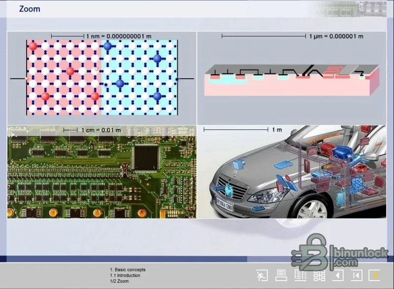
The lessons help connect a wiring-diagram symbol or board component to its role in the complete system. Understanding signal conditioning, memory type and output stages makes it easier to decide where to measure and why a controller may reset, lose stored data or fail to drive an actuator.
The course uses older Macromedia Director, Flash and InstallShield components. Modern Windows security settings may block or limit them, and browser-based Flash support is not expected. Run the local course only inside an isolated lab or virtual machine, keep networking disabled if it is not needed and do not lower security on a production diagnostic computer.
The course teaches general principles and is not tied to a complete vehicle-model list. It does not include modern secure-boot procedures, current gateway security, every network protocol or model-specific repair values. Use current manufacturer training and datasheets for modern controllers, high-voltage systems and safety-critical modules.
Theory does not remove bench risk. Use current-limited power, ESD protection, insulated probes and a verified pinout. Never power an unknown ECU solely from connector appearance, and do not practice soldering or destructive tests on a customer module.
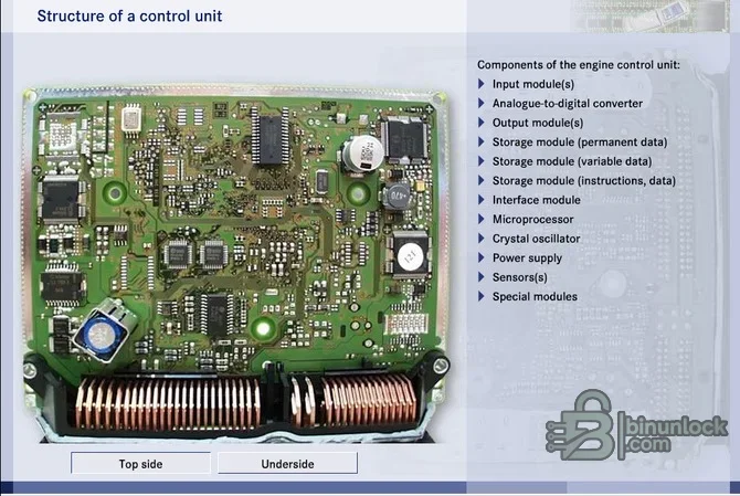
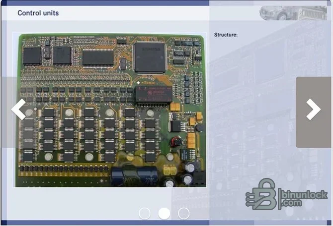
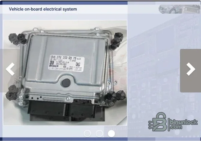
It is suitable for technicians learning why a control unit needs regulated power, clock and reset circuits, input conditioning, processors, memory and output drivers. The course provides theory and visual context; actual board repair still requires schematics, safe measurement techniques and identification of the exact controller hardware.
Course structure and confirmed topics#
- Three separate course parts with interactive navigation
- Semiconductor and basic electronic component principles
- Printed-circuit-board construction and component identification
- Control-unit input, processing and output architecture
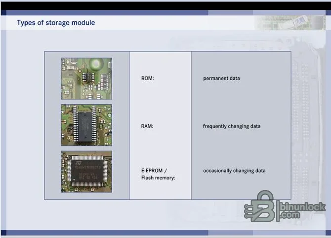
- ROM, RAM, EEPROM and flash-memory roles
- Scale from individual electronic devices to complete vehicle systems
- Audio narration, diagrams, animations and printable content
- Integrated technical glossary
What technicians can learn#
The lessons help connect a wiring-diagram symbol or board component to its role in the complete system. Understanding signal conditioning, memory type and output stages makes it easier to decide where to measure and why a controller may reset, lose stored data or fail to drive an actuator.
Computer and display requirements#
- Isolated Windows environment suitable for legacy 32-bit Director and Flash content
- Local extraction of the complete directory tree; do not run individual files from inside the archive
- Audio output for narrated lessons
- Standard desktop display and mouse for interactive navigation
- Enough disk space for all three parts and temporary print files
- No network connection is required for the packaged course
Legacy runtime considerations#
The course uses older Macromedia Director, Flash and InstallShield components. Modern Windows security settings may block or limit them, and browser-based Flash support is not expected. Run the local course only inside an isolated lab or virtual machine, keep networking disabled if it is not needed and do not lower security on a production diagnostic computer.
Recommended learning path#
- Complete the component and semiconductor lessons before jumping to ECU repair topics.
- Study power supply, reset and clock blocks, then trace how sensor inputs are conditioned.
- Compare memory types and note which data is temporary, fixed or electrically rewritable.
- Follow processor outputs through drivers, relays, solenoids and motors.
- Use the glossary when a circuit or memory term is unfamiliar.
- Apply the theory to a known spare ECU with a schematic and current-limited bench supply.
Workshop applications#
- Training new diagnostic or electronics technicians
- Preparing for board-level measurement and component identification
- Understanding why EEPROM and flash operations carry different risks
- Explaining control-unit architecture before oscilloscope practice
- Building a structured fault-isolation process from power input to actuator output
Coverage and limitations#
The course teaches general principles and is not tied to a complete vehicle-model list. It does not include modern secure-boot procedures, current gateway security, every network protocol or model-specific repair values. Use current manufacturer training and datasheets for modern controllers, high-voltage systems and safety-critical modules.
Troubleshooting course playback#
- Start screen does not open: verify the full tree was extracted and use a compatible isolated Windows environment
- Audio missing: check local sound output and confirm MP3 assets remain beside the lesson files
- Animation blank: the legacy Director or Flash runtime may be blocked by the host
- Print view fails: open the printable asset from the course directory or use a virtual PDF printer
- Navigation resets: avoid moving or renaming subfolders after extraction
Safe electronics practice#
Theory does not remove bench risk. Use current-limited power, ESD protection, insulated probes and a verified pinout. Never power an unknown ECU solely from connector appearance, and do not practice soldering or destructive tests on a customer module.


