
UniDiag KWP2000 is a portable Windows diagnostic application for older Alfa Romeo, Fiat and Lancia control units that communicate over the single-wire K-Line. It combines ECU identification, diagnostic-trouble-code handling and configurable live-data display with a library of vehicle and controller definition files.
This is a configurable legacy workshop tool rather than a modern automatic vehicle scanner. A definition-file name is useful compatibility evidence, but it is not a promise that every model year, ECU part number or wiring variant will connect. Confirm the controller label, protocol, diagnostic pin and interface before opening a session.
UniDiag does not automatically identify an unknown ECU and it does not turn a basic cable into a universal multi-brand scanner. Functions depend on the actual controller, the selected definition and the quality of the physical connection.
These labels identify supplied communication definitions, not a complete vehicle application list. Engine code, ECU hardware/software number and diagnostic implementation can change within the same model. Compare the physical ECU label and, where available, the definition header before connecting.
The package also contains a Bosch ABS 5.7 ASR/TC test definition and generic body, network and powertrain DTC dictionaries. The ABS file is explicitly marked as a test profile, so it should be treated as experimental rather than advertised as production coverage.
An ELM327 device is not a drop-in substitute for a raw KKL interface in this workflow. Likewise, this K-Line application should not be presented as a CAN or UDS diagnostic platform. Later vehicles and ECUs that communicate only over CAN require different hardware and software.
Start with the definition matching the controller, not merely the car badge. If a profile connects but returns implausible data, stop and verify that the ECU software family and request layout really match. Incorrect definitions can produce timeouts, negative responses or values that look numeric but have the wrong scaling.
For live data, select only parameters provided by the active definition and compare them with operating conditions. Engine speed should agree with the tachometer, coolant temperature should be credible for a cold or warm engine, and pressure or airflow readings must use the expected units. A smooth graph is not proof that the selected scaling is correct.
Do not clear faults before recording them. Erasing codes can remove useful diagnostic context and will not repair wiring, sensors, mechanical faults or communication problems.
The executable is unsigned and old. Use it on a dedicated workshop computer or a disposable virtual/physical Windows environment, keep current security controls in place and do not use the diagnostic laptop for unrelated personal accounts.
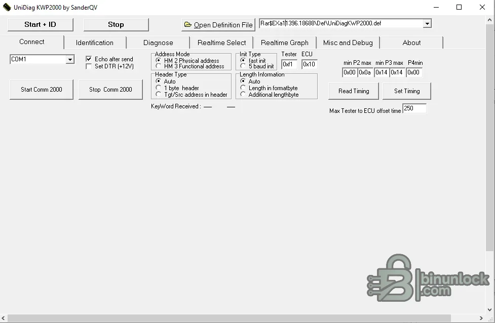
The source RAR was fully tested and extracted, and the executable was inspected statically without being launched. It is an unsigned 32-bit native Windows program; static analysis does not constitute a malware-clean guarantee. The original application screenshot is retained unchanged as the main image because it accurately shows the supplied build and contains no personal username or account data.
Use diagnostic functions only on vehicles you own or are authorized to service. Do not probe safety modules with guessed addresses, change connection pins while powered or clear evidence before documenting the complaint. A successful connection is the start of diagnosis, not proof that the selected ECU definition is correct.
This is a configurable legacy workshop tool rather than a modern automatic vehicle scanner. A definition-file name is useful compatibility evidence, but it is not a promise that every model year, ECU part number or wiring variant will connect. Confirm the controller label, protocol, diagnostic pin and interface before opening a session.
What UniDiag can do#
The main window exposes the complete connection rather than hiding it behind automatic detection. The operator selects a definition file and serial port, then controls initialization, tester and ECU addresses, message headers, timing and communication speed. Once connected, the available definition can provide identification, fault-code and live-data functions.- Connect to a supported KWP2000 ECU through a K-Line/KL-compatible interface
- Read controller identification information defined by the selected profile
- Run diagnostic requests and interpret supported DTC status information
- Select, display and graph real-time parameters supplied by the definition file
- Adjust communication addresses, initialization method, baud rate, timing and headers for controlled troubleshooting
- Use generic KWP2000 and powertrain-DTC definitions as a starting point for supported controllers
UniDiag does not automatically identify an unknown ECU and it does not turn a basic cable into a universal multi-brand scanner. Functions depend on the actual controller, the selected definition and the quality of the physical connection.
Included Alfa Romeo ECU profiles#
The cleaned package retains the original controller definitions. The following names are taken directly from those files and describe the profiles supplied with this build:- Alfa Romeo 2.0 JTS — Bosch MED7.1.1
- Alfa Romeo 156 Selespeed — Bosch ME3.1
- Alfa Romeo 156 Twin Spark — Bosch M1.5.5, including the alternate N profile
- Alfa Romeo 156 V6 — Bosch ME2.1
- Alfa Romeo 166 2.0 V6 Turbo — Bosch ME2.1
- Alfa Romeo Twin Spark 16V — Bosch M1.5.5
- Example definitions for Alfa 166 JTD, Alfa Twin Spark M1.5.5 and EDC15 testing
These labels identify supplied communication definitions, not a complete vehicle application list. Engine code, ECU hardware/software number and diagnostic implementation can change within the same model. Compare the physical ECU label and, where available, the definition header before connecting.
Included Fiat and Lancia ECU profiles#
- Alfa/Fiat/Lancia 1.9 JTD — Bosch EDC15
- Alfa/Fiat/Lancia 1.9 and 2.4 JTD — Bosch EDC15C7
- Alfa/Fiat/Lancia 2.4 JTD — Bosch EDC15
- Alfa/Lancia 1.6, 1.8, 2.0 16V and turbo applications — Bosch ME7.3.1
- Alfa/Lancia 2.5 and 3.0 V6 — Bosch ME2.1
- Fiat 1.2 8V and 16V — Magneti Marelli IAW 5NF
- Fiat 1.2 16V — Bosch M1.5.5
- Fiat/Lancia 1.6 — Magneti Marelli IAW 49F
- Fiat Punto 1.9 JTD — Bosch EDC15
- Selespeed — Magneti Marelli CFC208F
The package also contains a Bosch ABS 5.7 ASR/TC test definition and generic body, network and powertrain DTC dictionaries. The ABS file is explicitly marked as a test profile, so it should be treated as experimental rather than advertised as production coverage.
KWP2000, K-Line and interface requirements#
KWP2000 is the diagnostic protocol standardized as ISO 14230; on the vehicles targeted by this package it is commonly transported over K-Line. The original UniDiag author describes a KKL interface linking the vehicle's K-Line and, for older systems, optional L-Line to a PC serial or USB port.- A genuine or well-built KKL/VAG-COM-style K-Line interface with a stable USB-to-serial driver
- A Windows COM port that remains visible and is not already opened by another application
- Correct vehicle-side pin routing: engine management commonly uses the standard K-Line position, while ABS, airbag or other modules may require a switched/modified interface or the correct adapter
- For older three-pin diagnostic connectors, the correct manufacturer-specific adapter and separate protected battery supply where required
- Stable vehicle voltage and ignition state during identification, DTC and live-data sessions
An ELM327 device is not a drop-in substitute for a raw KKL interface in this workflow. Likewise, this K-Line application should not be presented as a CAN or UDS diagnostic platform. Later vehicles and ECUs that communicate only over CAN require different hardware and software.
Definition files and connection parameters#
Each.def file supplies the service requests, addresses and data interpretation needed for a particular controller family. The screenshot shows controls for baud rate, COM port, tester and ECU addresses, fast or slow initialization, initialization address, header format and several timing parameters.Start with the definition matching the controller, not merely the car badge. If a profile connects but returns implausible data, stop and verify that the ECU software family and request layout really match. Incorrect definitions can produce timeouts, negative responses or values that look numeric but have the wrong scaling.
- Fast initialization: commonly used by KWP2000 controllers; use only when supported by the ECU
- Slow/5-baud initialization: relevant to some ISO 9141 and older K-Line sessions
- ECU and tester addresses: must match the controller's expected physical or functional addressing
- Baud rate and timing: incorrect values commonly cause no-response, intermittent connection or dropped live data
- Header settings: determine how requests are framed and cannot be guessed safely from another ECU family
Recommended diagnostic workflow#
- Record the vehicle model, year, engine code, ECU manufacturer, hardware/software number and current fault symptoms.
- Connect a maintained battery support unit when an extended diagnostic session is planned.
- Install the KKL interface driver and confirm its COM port in Windows Device Manager. Avoid very high virtual-port numbers if the legacy application does not list them.
- Verify the diagnostic connector and route the K-Line to the correct control-unit pin. Never bridge pins blindly.
- Choose the closest exact ECU definition, then compare its name and configuration with the controller label.
- Switch the ignition as required, connect and read identification before clearing anything.
- Save the original DTC list and freeze-frame or live-data evidence relevant to the complaint.
- Monitor a small number of plausible parameters first. Stop if units, ranges or scaling are clearly wrong.
- After repair, repeat the same checks, clear faults only when appropriate and confirm that they do not return.
DTC and live-data use#
The package includes controller-specific and generic DTC dictionaries for powertrain, body and network faults. Generic text can help interpret a standardized code, but manufacturer-specific subcodes and status bytes may require workshop documentation for the exact vehicle.For live data, select only parameters provided by the active definition and compare them with operating conditions. Engine speed should agree with the tachometer, coolant temperature should be credible for a cold or warm engine, and pressure or airflow readings must use the expected units. A smooth graph is not proof that the selected scaling is correct.
Do not clear faults before recording them. Erasing codes can remove useful diagnostic context and will not repair wiring, sensors, mechanical faults or communication problems.
System requirements#
- 32-bit or 64-bit Windows computer capable of running a legacy x86 desktop application
- Windows XP or Windows 7 is the most period-appropriate environment; newer Windows versions may require a compatible USB-serial driver and legacy application settings
- Approximately 10 MB of free storage for the application, definitions and saved logs, plus space for workshop records
- One available physical or USB virtual COM port
- KKL/K-Line interface and any vehicle-specific three-pin or control-unit pin-routing adapters
- Display resolution of at least 1024 × 768 for comfortable access to the diagnostic and graph windows
- No internet connection or online account is required by the packaged application
The executable is unsigned and old. Use it on a dedicated workshop computer or a disposable virtual/physical Windows environment, keep current security controls in place and do not use the diagnostic laptop for unrelated personal accounts.
Troubleshooting common connection problems#
- COM port does not appear: install the correct interface driver, reconnect the cable and confirm that no other diagnostic program has opened the port
- Port opens but ECU does not answer: check ignition, battery voltage, K-Line pin routing, ground, interface type, initialization method, baud rate and ECU address
- Only the engine ECU connects: ABS, airbag and other modules may use different diagnostic pins or an older protocol; use the correct switched adapter and do not assume this KWP2000 build covers a KWP71 module
- Connection drops during live data: reduce the selected parameter count, check USB power management and cable quality, then restore the definition's known timing values
- Identification works but values are wrong: the selected definition may belong to another ECU software family; disconnect and verify the hardware/software number
- DTC text is missing or generic: retain the exact code and status bytes and consult documentation for the controller rather than inventing a description
Package contents and safety notes#
The cleaned archive contains the UniDiag executable, the full suppliedDef library and the combined Fiat/Lancia/Alfa DTC file: 35 functional files in total. A stale Iso9141.log containing an old COM2 timeout session was excluded because it is generated runtime residue, not program data.The source RAR was fully tested and extracted, and the executable was inspected statically without being launched. It is an unsigned 32-bit native Windows program; static analysis does not constitute a malware-clean guarantee. The original application screenshot is retained unchanged as the main image because it accurately shows the supplied build and contains no personal username or account data.
Use diagnostic functions only on vehicles you own or are authorized to service. Do not probe safety modules with guessed addresses, change connection pins while powered or clear evidence before documenting the complaint. A successful connection is the start of diagnosis, not proof that the selected ECU definition is correct.


